Room criteria and serving-area plan
The purpose of each room, the building areas and systems it serves, known equipment, growth basis, pathway relationships, owner requirements, field inputs, and open decisions recorded before layout begins.
Room criteria, layouts, rack elevations, pathways, backbone relationships, power and cooling inputs, bonding, and discipline coordination for new construction, renovations, and tenant improvements.
Telecommunications spaces are part of the building distribution system. The room plan, rack elevations, pathways, riser, power and cooling inputs, bonding, and specifications must describe the same design.
The purpose of each room, the building areas and systems it serves, known equipment, growth basis, pathway relationships, owner requirements, field inputs, and open decisions recorded before layout begins.
Dimensioned room plans showing racks, cabinets, wall fields, cable management, working zones, doors, pathway entries, grounding locations, and the interfaces other disciplines must preserve.
Equipment allocation, patching and cable-management intent, fiber and copper termination fields, reserved capacity, mounting relationships, and elevation notes developed to the contracted design phase.
Entrance conduits, riser sleeves, cable tray, ladder rack, backbone routes, penetrations, service loops, transitions, and capacity assumptions tied back to the building distribution design.
ICT loads and connection needs documented for the responsible electrical and mechanical designers, plus the telecommunications bonding topology and room-side connection requirements.
Room, rack, equipment, pathway, and grounding schedules as scoped, coordinated details, tracked comments, controlled revisions, and a pre-issue check across plans, risers, elevations, and specifications.
The first test is whether each space can serve its assigned area and connect to entrance and backbone pathways without creating avoidable distance, access, coordination, or resilience problems.
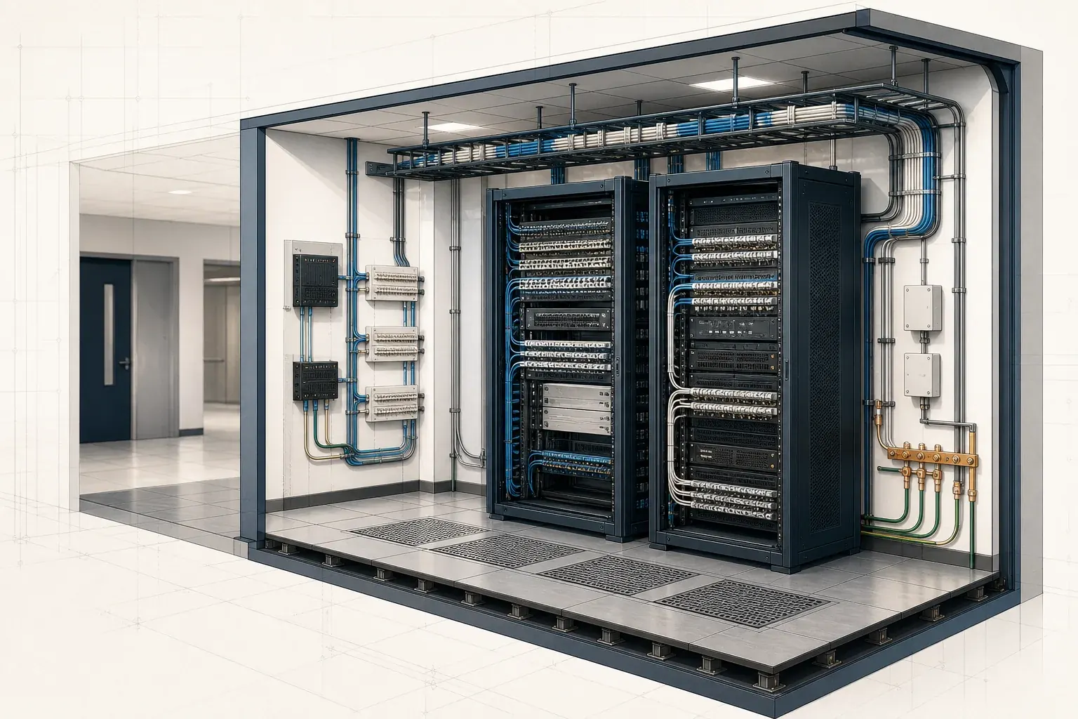
A beautifully drafted room in the wrong location can still force extra rooms, noncompliant link lengths, difficult backbone routes, or late architectural changes. Location and serving-area logic come first.
Formal standards and owner documents may use entrance facility, equipment room, telecommunications room, and telecommunications enclosure. Project teams often say MDF and IDF. The design translates the terminology into a clear serving and equipment function.
| Space term | Typical function | Decisions the project must record |
|---|---|---|
| Entrance facility (EF) | Carrier and outside-plant transition into the building. | Service entrance route, protection, bonding, provider demarcation, indoor transition, and relationship to the serving equipment room. |
| Equipment room (ER) | Building- or campus-serving telecommunications equipment and cross-connect functions. | Core equipment program, backbone distribution, access, environment, pathway concentration, resilience, and long-term maintenance. |
| Telecommunications room (TR) | Floor- or area-serving horizontal and backbone distribution. | Serving-area coverage, rack and wall capacity, horizontal pathways, backbone links, local equipment, power, cooling, bonding, and growth. |
| Telecommunications enclosure (TE) | A smaller serving space used only where the project criteria support it. | Equipment limitations, access, environment, serving area, pathway capacity, maintenance method, and owner acceptance. |
A single room can perform more than one function when the applicable standards, owner requirements, equipment program, pathways, environment, and project team support that arrangement. The drawing set should state the combined function rather than assume everyone interprets “MDF” the same way.
Renovation layouts are only as reliable as the inputs behind them. The engagement names who measures, photographs, scans, traces, opens, and verifies each existing condition before it becomes a design constraint.
The RCDD-led room design documents ICT intent and gives every responsible discipline the inputs it needs. It does not silently absorb electrical, mechanical, architectural, structural, or life-safety design responsibility.
Room location, dimensions, access route, door swing, wall construction, finishes, security, ceiling condition, and reserved wall area.
Normal and standby power needs, receptacles, panels and equipment kept outside working zones, surge or UPS interfaces, and connection to the building grounding system.
Equipment heat-load basis, continuous environmental requirements, controls, condensation risk, ventilation or cooling equipment, and maintenance access.
Rack, cabinet, tray, overhead support, wall-field, anchorage, and seismic requirements assigned to the appropriate designer or delegated engineer.
Rated construction, penetrations, firestopping, detection or suppression interfaces, and restrictions on unrelated systems routed through the room.
Network equipment, rack allocation, redundancy, carrier strategy, access control, monitoring, labeling, spares, and future-growth assumptions.
Constructability, approved products, shop drawings, installation sequencing, testing, record documents, and field verification without transferring design decisions by accident.
The exact phase names follow the prime contract. The sequence keeps room decisions tied to the building distribution design instead of treating the room as an isolated equipment diagram.
Map serving areas, cabling-distance constraints, backbone and entrance routes, vertical alignment, access, building separations, and owner standards. A room in the wrong place cannot be fixed by a cleaner rack elevation.
List active equipment, termination fields, racks, cabinets, wall systems, cable management, spare capacity, power, cooling, security, and maintenance needs using confirmed inputs or clearly labeled assumptions.
Place racks, cabinets, wall fields, pathways, doors, bonding points, and service zones together. Check installation, replacement, patching, testing, cleaning, and future access—not only the day-one fit.
Issue room requirements to architecture, electrical, mechanical, structural, fire-protection, security, and the owner team; record decisions and update the same controlled backgrounds.
Cross-check plans, risers, elevations, details, schedules, and specifications. When scoped, review submittals and RFIs, assess changes, and verify closeout records against the issued intent.
Applicable editions, owner criteria, equipment data, jurisdictional requirements, and contract documents must be confirmed for each project. Public-owner guides are examples of project criteria, not universal requirements.
TIA’s official standard page for the pathways and spaces framework used in commercial telecommunications design.
BICSI’s official source for the current TDMM, including telecommunications spaces, distribution, bonding, power, testing, and project administration.
TIA’s publication notice describing the current generic telecommunications bonding and grounding standard for customer premises.
A public-owner example showing how room location, size, environment, pathways, equipment, and project-specific criteria are documented together.
RCDD review covers the agreed ICT room, pathway, cabling, and telecommunications bonding design responsibility. It does not replace a licensed PE, architect, code official, delegated engineer, or the installing contractor's obligation to coordinate and verify the work.
Need the complete building distribution package? Review structured cabling design services. Need the specification and responsibility framework? See Division 27 telecommunications design.
Starting a programming, milestone, or constructability review? Work through the free 72-item telecom room design checklist and assign every open decision to the project record.
The room design is approved and construction is approaching? Run the telecom installation make-ready checklist before racks, cable, and termination crews mobilize.
The most useful proposal inputs are the project phase, building plans, owner standards, room list, serving-area assumptions, known equipment, existing-condition records, and required deliverables.
Send the project phase, available backgrounds, room list, owner criteria, known equipment, existing-condition records, schedule, and required drawing formats. You'll get a direct fit assessment and a defined next step.